|
|
|
 |
|
|
 |
|
|
|
|
|
|
Electricity and Electrical Power
Farmersville Elementary
School, Spring 2009
Grade 5 |
|
|
|
|
| |
|
|
|
In this program, we first learned
that electricity is a stream of electrons flowing through
the metal in a wire. In most electrical wires, the metal
is copper, and it is covered by an insulating plastic.
Electrons are a part of the atoms that make up the metal.
When the atoms come together to form a metal, the electrons
come loose and move freely. A battery creates a force
on the electrons that makes them move, and this is an
electrical current, or electricity.
|
|
|
|
|
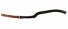
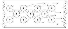
The picture on the left
below shows a real electrical wire, like the kind in the walls
of a house. The black part is the plastic insulation,
and the copper colored part, where the insulation was
removed, is the copper metal that carries the electrons
- the electricity. The drawing on the right shows how
the electrons come loose from the atoms that make up the
metal and flow through the wire.
|
|
|
|
|
|
| |
|
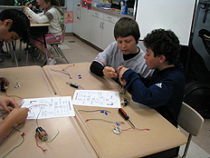
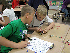
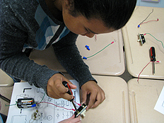
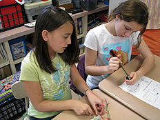
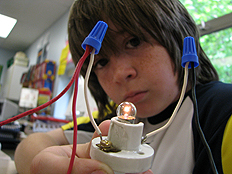
We learned how to make electrical
circuits. The electricity flows from a battery into
a switch. And not just a toy switch, but a real switch
from a real hardware store, just like in our house!
From the switch, the wire went to a light bulb, and
then back to the battery. This is a complete circuit
- starting and ending at the battery. We were given
electrical wiring diagrams to follow. Here we are carefully
examining the wiring diagrams. As you can see below, our teachers also built circuits.
|
|
|
|
|
|
|
|
|
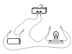
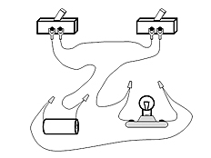
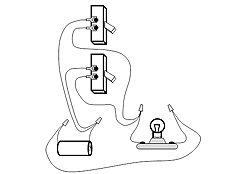
Here are the wiring diagrams we followed. From left to right, we have a simple circuit, a series circuit, and a parallel circuit.
|
|
|
|
|
|
| |
|
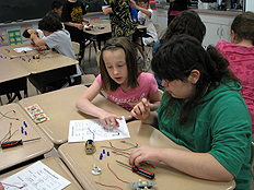
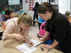
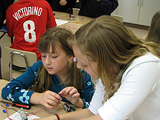
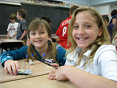
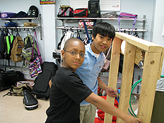
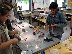
Finally, we began to construct our circuits. We connected wires to other wires using wire nuts. First you place the bare ends of two wires next to each other. Then you place the wire nut over both of them, like a hat. Finally, you twist the wire nut to tighten it. Rightsy-tightsy, lefty-loosey. Not only does the wire nut keep the wires from coming apart, it also holds them so tightly together that electric can flow from one to the other. We used a screw driver to connect wires to the real switches, just like we were grown-ups.
|
|
|
|
|
|
|
|
|
And, it worked!! After we wired the simple circuit, we made more complicated circuits using two switches, the series and parallel circuits.
|
|
|
|
|
|
| |
|
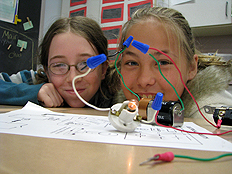
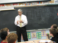
Dr. DeLeo said that series and parallel circuits were like computers since they could make decisions. The series arrangement of switches is called an AND gate because the light only lights up if switch 1 AND switch 2 are on. The parallel arrangement of switches is called an OR gate because the light lights up if switch 1 OR switch 2 are on. This idea is the basis for computers, digital watches, video games, and many of the electrical devices we use every day.
|
|
|
|
|
|
| |
|
|
|
Dr. DeLeo brought in a make believe wall so we could see what the wires look like in the walls of our house. The wires in the make-believe wall get their electricity from a battery, so it was safe to touch it. BUT!! .. Dr. DeLeo told us that we should never touch the wires in a real wall since that would be very, very dangerous! The wires in the walls of our house use high voltage. The make believe wall had a switch that turned on a light, and a button that made a door bell ring. We had fun making noise with the door bell. We got to ring the door bell every time we got one of our circuits to work.
|
|
|
|
|
|
|
We learned that electricity and magnetism are related to each other. Electricity can be used to make magnetism, as in an electromagnet. An electric motor works by turning a coil of wire into an electromagnet. This electromagnet is pushed by regular (permanent) magnets, and thats what makes the motor turn. Magnetism can be used to make electricity, as in a generator.
|
|
|
|
| |
|
|
|
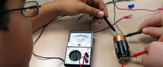
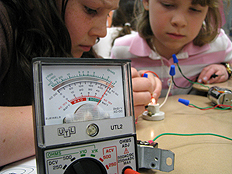
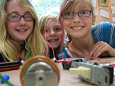
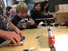
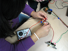
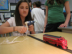
A generator takes the energy of motion and turns it into electrical energy. Dr. DeLeo had us turn the cranks on hand-held generators to make electricity. We used the electricity to light up little light bulbs and turn electric motors. We also used the electricity to make a toy train run on tracks. We also generated electricity by using the energy from light, by using solar cells. We got to use special meters to measure the amount of electricity in our circuits.
|
|
|
|
|
|
| |
|
Dr. DeLeo conected together a lot of hand generators so we could make enough electricity to light up a string of Christmas lights. Click the play button on the picture on the right to see a video.
|
|
|
|
|
|
|
At the end of the program, Dr. DeLeo gave each of us a magnetic field viewer. When we place it on top of a magnet, we can see the "magnetic field." They are so cool!
|
|
|
|
|
|
|
I hope you have enjoyed this web presentation as much as we enjoyed sharing the actual learning experience with your son or daughter. Although we have endeavored to exclude photographs where permission has been denied, it is possible for errors to occur. If you would like us to remove a photograph of your son or daughter for any reason, please send me an e-mail message at lgd0@lehigh.edu or call me at 610-758-3413, and we will remove it promptly. Please note that we will never associate a child's full or last name with a photograph except in circumstances where special permission was explicitly provided. Thank you. Gary DeLeo. |
|
|
|
|
|
|
|
|